Imagine you just opened a new restaurant and hired a single chef to run the kitchen. At first, business is slow, and the chef can easily handle every order alone. But as word spreads, more and more customers start pouring in. Now the chef is frantically cooking for one table while the waiter brings orders from five others. The result? Long wait times and unhappy customers. The obvious fix? Hire more chefs! But then, how do you make sure the new orders get to a chef who’s actually free?
This exact problem shows up when your app runs on a single server (or node) and suddenly starts getting heavy traffic. Initially, the single server handles all requests smoothly. But as more users show up, the server is constantly busy, response times creep up, and overall throughput drops. So what do you do? You have two options:
- Vertical Scaling (Scaling up): You beef up your existing server by giving it more resources. Your app stays on one machine, but now it’s the “Hulk” among servers. For example: If your app was deployed on a server with 2 cores previously, you now deploy it on a server containing 8 cores.
- Horizontal Scaling (Scaling out): Instead of making one server huge, you add more servers. Multiple copies of your app run side by side. This is like hiring a whole team of chefs instead of just one. If vertical scaling made your server a Hulk, horizontal scaling is like deploying a squad of efficient minions. For example: If your app was deployed on one server with 2 cores previously, you now have 4 replicas of the same app deployed on 4 separate servers, each with 2 cores.
Both strategies come with their own trade-offs. Here are some challenges with vertical scaling:
- There is a limit to how big a single server can get, and the bigger it becomes, the more expensive it is to upgrade further.
- If your app only sees heavy traffic during certain hours, running a massive server all day wastes resources during off-peak times.
- If that one big server crashes, your app goes down completely until it is fixed. This is called a Single Point of Failure (SPOF).
To stay within the scope of load balancers, I won’t dive too deep into scalability details.
At the start, vertical scaling feels easier because you just give your server more power. But sooner or later, horizontal scaling becomes the best choice to help your app handle more traffic smoothly. So here is the question: how do you make sure incoming requests get shared fairly among all your app’s backend servers? This is where a load balancer steps in. Think of it as a smart traffic controller that receives client requests and then sends each one to the backend server best able to handle it at that moment.
Let us break down what a load balancer does for you:
1. Distributing Traffic
When you have multiple identical servers behind a load balancer, your system gains redundancy. The load balancer spreads incoming traffic evenly across those servers, thus mitigating the SPOF concern at the server level. As your traffic grows, you can add more servers, and the load balancer will automatically send traffic to them. This offers virtually limitless potential for growth compared to the finite limits of vertical scaling.
2. Preventing Overload & Optimizing Resource Utilization
Load balancers do not just send traffic randomly. They monitor how busy each server is. If one server is getting overwhelmed, that is, it reaches a predefined capacity threshold (e.g., CPU utilization, memory usage, or active connections), the load balancer will direct subsequent requests to less busy servers. This intelligent distribution prevents situations where some servers are idle or underutilized while others are operating at or beyond capacity.
3. Improving Performance
When the workload is distributed across multiple servers, more requests can be handled in parallel and each server handles fewer individual requests. This translates directly to lower latency and higher throughput for the entire system.
4. Ensuring Reliability
Load balancers continuously monitor the health of backend servers. If a server is recognized as unhealthy (e.g., server is unresponsive, it crashed, or went offline), the load balancer immediately detects this anomaly and stops sending it any new requests and redirects all subsequent requests to the remaining operational servers. This automatic failover mechanism allows the app to continue operating without interruption, ensuring robustness. These health checks ensure that individual component failures do not result in a complete system outage. Thus, load balancers help us build fault tolerance in our app.
5. Enabling High Availability
By eliminating single points of failure at the server level and providing seamless failover capabilities, load balancing significantly increases the overall uptime of applications and services, making them consistently available to users.
6. Zero Downtime Deployments
Maintenance or deploying software updates on production servers used to require scheduled downtime. With a load balancer, we can remove a specific server from the load balancer’s server pool, perform the update or maintaince operations on it in isolation, and then reintroduce it to the load balancer’s pool. This process can be repeated iteratively for each server in the pool, ensuring that the service remains continuously operational throughout the entire maintenance or update cycle.
Load balancing is not just an extra feature. It is indispensable if you want your system to perform well, be continuously availabile, and grow smoothly as demand rises.
Core Concepts
To really understand how load balancers work, it helps to walk through an example. Let’s imagine you’re building a system with two microservices:
order_svc: This one handles HTTPS requests that go to the/orderpath. You’ve deployed it across four backend servers: A, B, C, and D.image_svc: This service takes care of HTTPS requests to the/imagepath and is running on two backend servers: D and E.
Now, to manage the traffic going to these services, you place a load balancer in front of all five servers. These servers together form what is called the server pool, also known as a server farm. This is the group of machines the load balancer sends incoming requests to.
Definition: Server Pool is a logical grouping of multiple backend servers that are configured to handle the same type of requests.
In this setup, servers A, B, C, and D make up one target group. Let’s call it Target Group X, which handles the traffic for order_svc. Servers D and E form Target Group Y, which handles requests for image_svc.
Definition: A target group is a set of backend servers from the server pool that share a common purpose or behavior, like serving a specific type of request.
The load balancer also needs something called a listener. Think of a listener like someone standing at the front door, waiting for a knock. In our case, the listener is configured to listen for HTTPS requests on port 443. Once a request comes in, the listener checks the path and takes the appropriate action. For example, if it sees a request for /order, it will forward that request to Target Group X. If the request is for /image, it sends it to Target Group Y.
Definition: A listener is a part of the load balancer that waits for incoming requests on a specific protocol (like HTTP or HTTPS) and port. It is configured to take action when a request is received, such as forwarding it to the right target group. A single listener can send traffic to one or more target groups, depending on how it’s set up.
Health Checks
Imagine you’re managing a team, and before assigning a task, you want to make sure each team member is actually available and ready to work. Load balancers do something very similar. To avoid sending requests to servers that are down or unresponsive, they constantly monitor the health of backend servers inside each target group. This process is known as a health check.
Health checks ensure that only servers that are up and running receive traffic. If a server fails a check, the load balancer temporarily takes it out of the rotation until it recovers. Let’s walk through the common types of health checks:
-
TCP Health Check: This is a basic “is it alive and listening?” check. The load balancer tries to open a TCP connection to a specific port on the backend server. If it connects successfully, the server is marked as healthy at the network level. If no application is listening on that port, the server’s TCP stack replies with a
RST(reset) flag, which tells the load balancer that the connection is being actively rejected. This check operates at the transport layer (Layer 4 of the OSI model). -
HTTP/HTTPS Health Check: Instead of just checking if the server is listening, it tests if the application itself is responding properly. The load balancer sends an HTTP (or HTTPS)
GETrequest to a specific path (e.g.,/healthzor/status) on the backend server. The server is considered healthy if it returns a successful HTTP status code (e.g.,200 OK) within a defined timeframe. This is a good way to ensure the actual service (not just the server) is behaving as expected. -
UDP Health Check: This is useful for services using the UDP protocol. The load balancer sends a UDP packet to a chosen port and waits for a response, assuming the application is designed to reply. If there is no application listening on that port, the server’s network stack replies with an ICMP “Destination Port Unreachable” message. If the server itself is offline, the load balancer might receive an ICMP “Destination Host Unreachable” from a router along the way. This check operates at the network layer (Layer 3) unlike the TCP health check, which operates at the transport layer (Layer 4).
Sometimes, basic checks aren’t enough. You might want to verify that your application is not just up, but actually working as expected. For deeper validation, you can write custom scripts that run on both the load balancer and the backend servers.
There are also several parameters you can tweak to make the built-in health checks better suited for your application’s behavior:
- The load balancer sends health check probes to each backend server at a preconfigured frequency (in seconds), called Interval. A shorter interval detects failures faster but generates more network traffic.
- Then there’s the Timeout. This is how long the load balancer waits for a response from the server. If the server doesn’t reply within this time, the health check is considered failed.
- Now, consider this scenario: the server is perfectly fine, but due to a temporary network glitch, it doesn’t respond to a probe in time. Do we immediately take it out of the server pool? Or should we give it another chance? That’s where the Unhealthy Threshold comes in. This setting defines how many consecutive failed health checks it takes before a server is marked as unhealthy and removed from the rotation. Only after crossing this threshold will the load balancer stop sending it any new requests.
- On the flip side, a flapping server, a flapping server (one that is repeatedly going online and offline) might occasionally pass a health check while it happens to be online. But you probably don’t want to rely on such an unstable server too quickly. That’s why there’s also a Healthy Threshold, which defines how many successful checks are required before an unhealthy server is considered healthy again. Once it meets this threshold, the load balancer automatically re-adds it to the pool, and it starts receiving traffic again.
Tuning these parameters helps strike the right balance between being responsive to real failures and being resilient to short-lived glitches.
Load Balancer Placement
Modern, scalable applications are almost always built in multiple tiers, and load balancing plays a key role at every stage. In a well-architected multi-tier system, a single user request might pass through several load balancers as it travels from the client to the web tier, then to the application tier, and finally to the data tier. At each step, a load balancer ensures requests are handled efficiently and reliably.
Let’s take a look at how load balancers are strategically placed throughout this journey to improve performance, scalability, and fault tolerance.
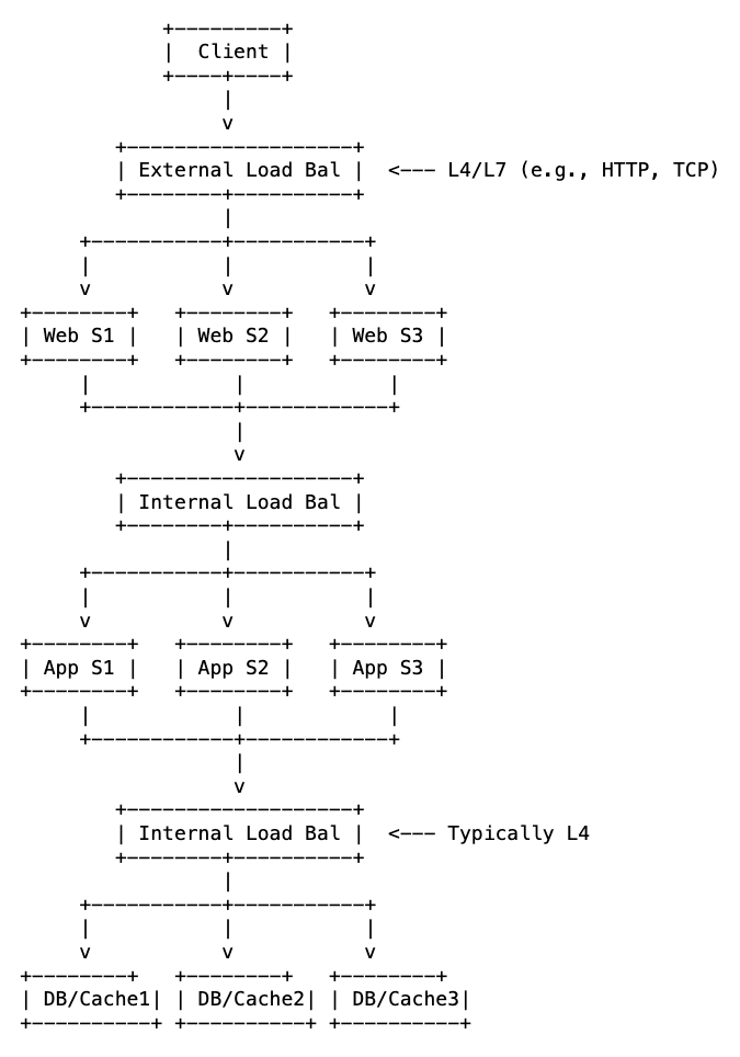
1. Between Client and Web Servers (External Load Balancing)
Here, the load balancer acts as the gateway between your users and your infrastructure. It sits between the public internet (or user devices) and your fleet of web servers. From the outside, users see only a single public IP address or domain name. Behind the scenes, the load balancer distributes incoming requests across multiple backend web servers.
This is also where you can offload some common request preprocessing. For example, SSL or TLS termination is often done here, which means the load balancer handles the encryption and decryption of HTTPS requests. This frees up your web servers to focus on processing actual content rather than dealing with heavy cryptographic operations. If the web servers are on the same internal network, the load balancer can even send them plain HTTP messages, simplifying the traffic internally.
2. Between Web Servers and Application Servers (Internal Load Balancing)
In many modern web applications, web servers are responsible only for static content like HTML, CSS, and images. Any dynamic or complex processing is handed off to a set of application servers.
A load balancer can be placed between the web servers and the application servers to manage this internal communication. It decouples the web tier from the application tier, allowing each to scale independently. Web servers forward requests to the application load balancer, which then distributes them to the application servers. This ensures that the workload on application servers is evenly distributed, optimizing their performance for complex computations.
3. Between Application Servers and Database/Cache Servers (Internal Load Balancing)
Even the data layer benefits from load balancing. A load balancer can sit between the pool of application servers and the pool of database servers (e.g., read replicas) or cache servers. The load balancer in this setup can manage persistent connections to databases, improving efficiency, and also ensures that if one database replica or cache node fails, application servers can still access data through other healthy instances. It also allows the databases and the application servers to scale independently.
Thus, load balancing at different junctures within our system allow each tier (web, application, data) to be scaled independently based on its specific load characteristics. Each tier can be maintained, updated, or debugged with minimal impact on other tiers.
Ultimately, load balancing is not just about handling more traffic. It’s about making each part of your architecture more reliable, more efficient, and better at doing what it’s supposed to do. Load balancers reduce bottlenecks at each communication point, ensuring faster overall response times.
Types of Load Balancers
The OSI model layer where a load balancer operates defines what kind of information it can access, interpret, and act upon in the network traffic. Let’s break down the different types, starting from the lowest layer and moving up.
1. Layer 2 Load Balancing (Data Link Layer)
Client -> Switch -> Load Balancer (L2) -> Backend Servers
At Layer 2, there’s no concept of IP addresses or ports. Each machine only has access to the MAC addresses of other machines within its local network segment.
When the load balancer receives a frame, it rewrites the destination MAC address to match the MAC address of the backend server it selects. It then sends the frame back to the switch. The switch, recognizing the destination MAC, forwards the frame to the correct server.
There’s another clever technique for achieving L2 load balancing called Gratuitous ARP Spoofing. In this setup, all the backend servers share one VIP (Virtual IP address). The load balancer periodically sends gratuitous ARP replies to the switch, dynamically associating the VIP with different servers’ MAC addresses over time. This causes the switch to forward traffic for the VIP to different servers based on the current ARP entry.
Definition: A VIP (Virtual IP address) is an IP address that is not bound to a single physical machine on a network. Instead, it is associated with a service or application and can be shared by multiple servers or devices. A VIP serves as a stable address that can represent either a single active server or a group of servers. Incoming traffic is directed to the VIP, and the network then routes it to the appropriate server or application based on its configuration. Both, the load balancer, and the backend servers might be associated with a VIP.
As we can see, L2 load balancing is strictly limited to a single local network segment (e.g., within one server rack or a single VLAN). It has no awareness of IP addresses, ports, or application content.
2. Layer 3 Load Balancing (Network Layer)
Client → Router → Load Balancer (L3) → Multiple Backend Servers
At this level, the load balancer can read and modify the IP headers in each packet. It knows the destination IP address and the transport protocol (like TCP or UDP) from the IP header, but nothing about ports or application-level data.
The most common technique used here is Destination Network Address Translation (DNAT). When a packet arrives, the load balancer rewrites the destination IP in the packet to point to the chosen backend server. It then forwards the modified packet to the router, which sends it to the appropriate server based on the updated IP.
There’s another approach using ECMP (Equal-Cost Multi-Path) routing. In this case, all backend servers advertise the same VIP. The router sees multiple valid paths to reach that VIP, each with the same cost (for example, same number of hops). The router then uses a hash of certain packet header fields, like source and destination IPs, to distribute traffic across those paths. As a result, packets are spread across multiple backend servers without the load balancer having to make per-packet decisions.
Definition: ECMP (Equal-Cost Multi-Path) is a routing strategy where packets are distributed across multiple paths that have the same routing cost. This helps improve throughput and redundancy in IP-based networks.
L3 load balancing is highly limited because it cannot inspect port numbers or application data. Therefore, it cannot differentiate between different services running on the same IP address. It also has no way to tell whether the backend application is healthy or even running. It simply ensures that packets are delivered to a destination IP address, and that’s it.
3. Layer 4 Load Balancers (Transport Layer)
At Layer 4, the load balancer works with TCP and UDP traffic. It looks at IP addresses and port numbers, but doesn’t peek into application-level data like HTTP headers or URLs.
When a client request comes in, the load balancer intercepts the TCP segment or UDP datagram. It performs Destination NAT (DNAT) to replace the destination IP (its own VIP) with the IP address of the selected backend server. If needed, it also updates the destination port in the packet, especially if the backend service listens on a different internal port. Once modified, the packet is forwarded to the chosen server.
For TCP traffic, there are two common ways the load balancer can handle the connection:
- Connection Termination (Proxy Mode): The load balancer completes the TCP handshake on behalf of the backend server. From the client’s perspective, it appears to be the actual server. Internally, the load balancer then opens a new TCP connection to the selected backend. To improve performance, it might keep a pool of open connections to the backend and reuse them across requests avoiding the need to open a brand new TCP connection to the backend for every request.
- Connection Pass-Through (Transparent Mode): Here, the load balancer doesn’t terminate the connection. Instead, it acts as a router or NAT device, simply forwarding TCP packets between the client and the backend. The backend server completes the TCP handshake directly with the client, that is, the
SYNandACKflags are directly exchanged between the client and the backend server.
Depending on the network setup, the load balancer may also modify the source IP address in outgoing packets using Source NAT (SNAT):
- If SNAT is used, response traffic returns to the load balancer, which then forwards it back to the client.
- If SNAT is not used, the backend server can respond directly to the client. This is known as Direct Server Return (DSR).
Note: DSR is not possible if the load balancer terminates the client TCP connection (Proxy Mode), because the backend server is unaware of the original connection state.
There might be scenarios where the backend servers need IP addresses of clients for things like analytics, rate limiting, access control, etc. But the system might be set up in a way to send the responses back through the load balancer. That’s where Proxy Protocol mode comes in. The load balancer prepends a small, text-based header (the Proxy Protocol header) to the beginning of the data stream. This header contains the client’s original source IP address and port, the load balancer’s source IP and port, and other connection details. The backend application servers must be configured to understand and parse this Proxy Protocol header before processing the actual application data. They can read the client’s original IP from this header.
Note: Proxy Protocol is typically used with TCP-based protocols.
Why use Layer 4 load balancing?
By avoiding deep packet inspection and complex application-layer processing, Layer 4 load balancers are extremely fast and efficient. They handle connection setup and forwarding with minimal overhead, leading to very low latency. Their efficiency allows them to manage a very large number of concurrent connections and process massive volumes of data per second.
L4 load balancers can load balance any protocol that uses TCP or UDP as its transport layer. This includes HTTP, HTTPS, FTP, SSH, DNS, gaming protocols, database connections (e.g., MySQL, PostgreSQL), and custom binary protocols.
Due to their lack of application-layer visibility, they cannot perform advanced functions like SSL/TLS termination, HTTP header manipulation, URL-based routing, cookie-based session stickiness, content caching, compression, or Web Application Firewall (WAF) features directly. For these, you need a Layer 7 load balancer.
4. Layer 7 Load Balancers (Application Layer)
Layer 7 load balancers work at the Application Layer, which gives them full visibility into the details of web traffic. They can inspect entire HTTP and HTTPS messages, including headers, URL paths, query parameters, HTTP methods, cookies, and even the body of the request. This makes them incredibly powerful for routing decisions based on content, user identity, or application logic.
Unlike lower-level load balancers, a Layer 7 load balancer always acts as a full proxy. It manages two separate network connections: one with the client and another with the backend server. Here’s how that plays out:
- For TCP, the load balancer completes the entire TCP three-way handshake with the client.
- For HTTPS, it also performs SSL/TLS termination. That means it handles encryption and decryption on behalf of the backend, reducing the cryptographic burden on your servers. Depending on your setup, it can either send unencrypted traffic to the backend or re-encrypt it before forwarding.
Based on its load balancing algorithm, sophisticated routing rules (e.g., “if URL path starts with /api/, send to API servers”), and application-aware health checks, the load balancer selects the optimal backend server.
The request is forwarded to the selected backend server over a separate connection. This connection can be freshly opened or reused from a connection pool. The load balancer may also modify the request, such as adding an X-Forwarded-For header to pass along the original client’s IP address.
Once the backend processes the request, it sends a response back to the load balancer, which then relays it to the client over the original connection. If the traffic is HTTPS, it re-encrypts the response before sending it.
Why use Layer 7 load balancing?
Because it enables smart, content-aware traffic routing.
- In microservices architectures, where different services are mapped to different paths, Layer 7 routing ensures the right request goes to the right service.
- In multi-tenant setups, where multiple applications share the same domain, you can route traffic based on the URL path or domain subcomponent.
- You can enforce security policies by inspecting traffic for attack patterns, such as SQL injection or cross-site scripting, and block malicious requests before they hit your servers.
- You can serve cached static content directly from the load balancer, which reduces backend load and speeds up response times.
- You can apply compression to reduce bandwidth usage and improve load times for clients.
- You can enforce session stickiness, routing requests from a given client to the same backend server to preserve session state.
All this power comes at a cost. Because Layer 7 load balancers terminate connections, inspect traffic deeply, and often modify it, they introduce more latency and consume more CPU resources than simpler load balancers. But in return, you get the fine-grained control that modern applications often need.
Use Cases
| Load Balancing Type | OSI Layer | Real-World Application Examples |
|---|---|---|
| Layer 2 Load Balancing | Data Link Layer (MAC addresses) | - Network Interface Card (NIC) Teaming/Bonding: Combining multiple physical NICs on a server for increased bandwidth and redundancy. - Switch-based load balancing: Distributing traffic across multiple links or physical server ports within a local segment. |
| Layer 3 Load Balancing | Network Layer (IP addresses) | - Routing traffic to multiple gateways or routers. - DNS-based Global Server Load Balancing (GSLB): Directing users to different data centers based on DNS lookups (though DNS itself is L7, the decision is often IP-based). - ECMP (Equal-Cost Multi-Path) Routing: Routers distributing traffic across multiple equal-cost paths to a destination IP. |
| Layer 4 Load Balancing | Transport Layer (IP addresses + Ports) | - Distributing client connections to database instances. - Gaming servers: Handling high volumes of TCP or UDP traffic for online multiplayer games where content inspection isn’t needed for routing decisions. - FTP servers: Balancing file transfer sessions. - Real-time streaming (non-HTTP): Distributing raw audio/video streams. - SMTP servers: Balancing email traffic. |
| Layer 7 Load Balancing | Application Layer (HTTP, HTTPS, FTP, etc.) | - Routing based on URL path in web applications and APIs. - E-commerce platforms: Maintaining “sticky sessions” based on cookies for shopping carts or login sessions. - A/B Testing: Routing a percentage of users to a “new feature” version of an application. - Multi-tenant apps |
Summary: The further “up” the OSI stack a load balancer operates (e.g., Layer 7 vs. Layer 4), the more application-specific information it can understand, enabling more complex and intelligent routing decisions, but often at the cost of higher processing overhead.
That’s it for this one!
In the next post, we’ll peek under the hood of load balancing algorithms and see how they actually make decisions. Until then, may your traffic be evenly distributed and your servers stay cool.
Thanks for reading!